87010941_0_20200117Datenblatt.pdf
Dieses Dokument ist Teil der Anfrage „Standortbescheinigungen 011217, 018148, 011921, 018397 und 87010941“
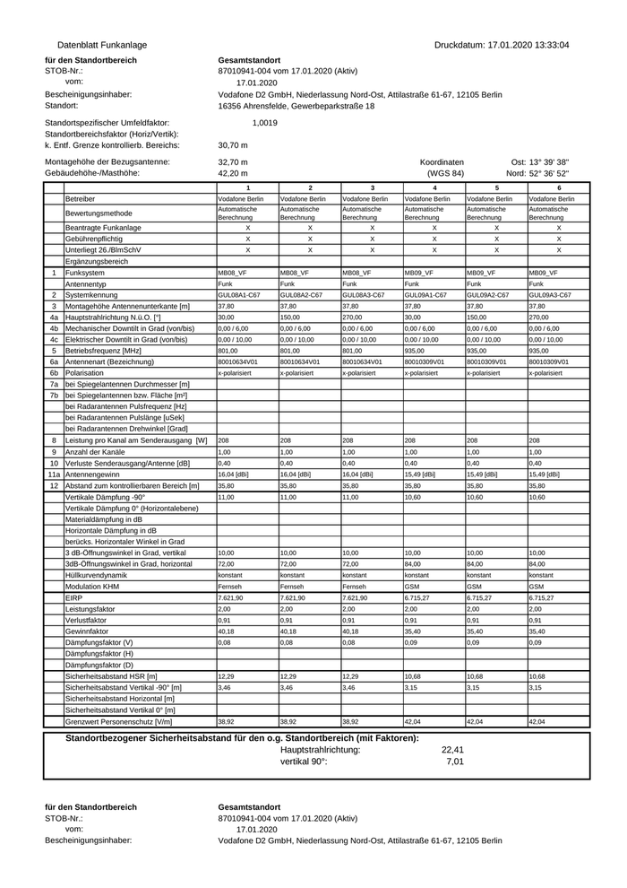
Datenblatt Funkanlage für den Standortbereich STOB-Nr.: vom: Bescheinigungsinhaber: Standort: Druckdatum: 17.01.2020 13:33:04 Gesamtstandort 87010941-004 vom 17.01.2020 (Aktiv) 17.01.2020 Vodafone D2 GmbH, Niederlassung Nord-Ost, Attilastraße 61-67, 12105 Berlin 16356 Ahrensfelde, Gewerbeparkstraße 18 Standortspezifischer Umfeldfaktor: Standortbereichsfaktor (Horiz/Vertik): k. Entf. Grenze kontrollierb. Bereichs: 1,0019 30,70 m Montagehöhe der Bezugsantenne: Gebäudehöhe-/Masthöhe: 32,70 m 42,20 m Koordinaten (WGS 84) 1 2 3 Ost: 13° 39' 38'' Nord: 52° 36' 52'' 4 5 6 Betreiber Vodafone Berlin Vodafone Berlin Vodafone Berlin Vodafone Berlin Vodafone Berlin Vodafone Berlin Bewertungsmethode Automatische Berechnung Automatische Berechnung Automatische Berechnung Automatische Berechnung Automatische Berechnung Automatische Berechnung Beantragte Funkanlage X X X X X X Gebührenpflichtig X X X X X X Unterliegt 26./BlmSchV X X X X X X Ergänzungsbereich 1 Funksystem MB08_VF MB08_VF MB08_VF MB09_VF MB09_VF MB09_VF Funk Funk Funk Funk Funk Funk 2 Antennentyp Systemkennung GUL08A1-C67 GUL08A2-C67 GUL08A3-C67 GUL09A1-C67 GUL09A2-C67 GUL09A3-C67 3 Montagehöhe Antennenunterkante [m] 37,80 37,80 37,80 37,80 37,80 37,80 4a Hauptstrahlrichtung N.ü.O. [°] 30,00 150,00 270,00 30,00 150,00 270,00 4b Mechanischer Downtilt in Grad (von/bis) 0,00 / 6,00 0,00 / 6,00 0,00 / 6,00 0,00 / 6,00 0,00 / 6,00 0,00 / 6,00 4c Elektrischer Downtilt in Grad (von/bis) 0,00 / 10,00 0,00 / 10,00 0,00 / 10,00 0,00 / 10,00 0,00 / 10,00 0,00 / 10,00 5 Betriebsfrequenz [MHz] 801,00 801,00 801,00 935,00 935,00 935,00 6a Antennenart (Bezeichnung) 80010634V01 80010634V01 80010634V01 80010309V01 80010309V01 80010309V01 6b Polarisation x-polarisiert x-polarisiert x-polarisiert x-polarisiert x-polarisiert x-polarisiert 7a bei Spiegelantennen Durchmesser [m] 7b bei Spiegelantennen bzw. Fläche [m²] bei Radarantennen Pulsfrequenz [Hz] bei Radarantennen Pulslänge [uSek] bei Radarantennen Drehwinkel [Grad] 8 Leistung pro Kanal am Senderausgang [W] 208 208 208 208 208 208 9 Anzahl der Kanäle 1,00 1,00 1,00 1,00 1,00 1,00 0,40 0,40 0,40 0,40 0,40 0,40 16,04 [dBi] 16,04 [dBi] 16,04 [dBi] 15,49 [dBi] 15,49 [dBi] 15,49 [dBi] 35,80 35,80 35,80 35,80 35,80 35,80 11,00 11,00 11,00 10,60 10,60 10,60 3 dB-Öffnungswinkel in Grad, vertikal 10,00 10,00 10,00 10,00 10,00 10,00 3dB-Öffnungswinkel in Grad, horizontal 72,00 72,00 72,00 84,00 84,00 84,00 Hüllkurvendynamik konstant konstant konstant konstant konstant konstant Modulation KHM Fernseh Fernseh Fernseh GSM GSM GSM EIRP 7.621,90 7.621,90 7.621,90 6.715,27 6.715,27 6.715,27 Leistungsfaktor 2,00 2,00 2,00 2,00 2,00 2,00 Verlustfaktor 0,91 0,91 0,91 0,91 0,91 0,91 Gewinnfaktor 40,18 40,18 40,18 35,40 35,40 35,40 Dämpfungsfaktor (V) 0,08 0,08 0,08 0,09 0,09 0,09 Sicherheitsabstand HSR [m] 12,29 12,29 12,29 10,68 10,68 10,68 Sicherheitsabstand Vertikal -90° [m] 3,46 3,46 3,46 3,15 3,15 3,15 38,92 38,92 38,92 42,04 42,04 42,04 10 Verluste Senderausgang/Antenne [dB] 11a Antennengewinn 12 Abstand zum kontrollierbaren Bereich [m] Vertikale Dämpfung -90° Vertikale Dämpfung 0° (Horizontalebene) Materialdämpfung in dB Horizontale Dämpfung in dB berücks. Horizontaler Winkel in Grad Dämpfungsfaktor (H) Dämpfungsfaktor (D) Sicherheitsabstand Horizontal [m] Sicherheitsabstand Vertikal 0° [m] Grenzwert Personenschutz [V/m] Standortbezogener Sicherheitsabstand für den o.g. Standortbereich (mit Faktoren): Hauptstrahlrichtung: vertikal 90°: für den Standortbereich STOB-Nr.: vom: Bescheinigungsinhaber: 22,41 7,01 Gesamtstandort 87010941-004 vom 17.01.2020 (Aktiv) 17.01.2020 Vodafone D2 GmbH, Niederlassung Nord-Ost, Attilastraße 61-67, 12105 Berlin

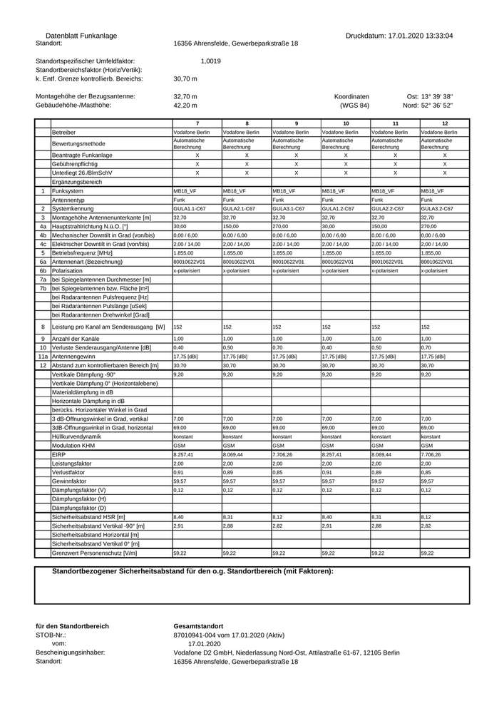
Datenblatt Funkanlage Standort: Druckdatum: 17.01.2020 13:33:04 16356 Ahrensfelde, Gewerbeparkstraße 18 Standortspezifischer Umfeldfaktor: Standortbereichsfaktor (Horiz/Vertik): k. Entf. Grenze kontrollierb. Bereichs: 1,0019 30,70 m Montagehöhe der Bezugsantenne: Gebäudehöhe-/Masthöhe: 32,70 m 42,20 m Koordinaten (WGS 84) 7 8 9 Ost: 13° 39' 38'' Nord: 52° 36' 52'' 10 11 12 Betreiber Vodafone Berlin Vodafone Berlin Vodafone Berlin Vodafone Berlin Vodafone Berlin Vodafone Berlin Bewertungsmethode Automatische Berechnung Automatische Berechnung Automatische Berechnung Automatische Berechnung Automatische Berechnung Automatische Berechnung Beantragte Funkanlage X X X X X X Gebührenpflichtig X X X X X X Unterliegt 26./BlmSchV X X X X X X Ergänzungsbereich 1 Funksystem MB18_VF MB18_VF MB18_VF MB18_VF MB18_VF MB18_VF Funk Funk Funk Funk Funk Funk 2 Antennentyp Systemkennung GULA1.1-C67 GULA2.1-C67 GULA3.1-C67 GULA1.2-C67 GULA2.2-C67 GULA3.2-C67 3 Montagehöhe Antennenunterkante [m] 32,70 32,70 32,70 32,70 32,70 32,70 4a Hauptstrahlrichtung N.ü.O. [°] 30,00 150,00 270,00 30,00 150,00 270,00 4b Mechanischer Downtilt in Grad (von/bis) 0,00 / 6,00 0,00 / 6,00 0,00 / 6,00 0,00 / 6,00 0,00 / 6,00 0,00 / 6,00 4c Elektrischer Downtilt in Grad (von/bis) 2,00 / 14,00 2,00 / 14,00 2,00 / 14,00 2,00 / 14,00 2,00 / 14,00 2,00 / 14,00 5 Betriebsfrequenz [MHz] 1.855,00 1.855,00 1.855,00 1.855,00 1.855,00 1.855,00 6a Antennenart (Bezeichnung) 80010622V01 80010622V01 80010622V01 80010622V01 80010622V01 80010622V01 6b Polarisation x-polarisiert x-polarisiert x-polarisiert x-polarisiert x-polarisiert x-polarisiert 7a bei Spiegelantennen Durchmesser [m] 7b bei Spiegelantennen bzw. Fläche [m²] bei Radarantennen Pulsfrequenz [Hz] bei Radarantennen Pulslänge [uSek] bei Radarantennen Drehwinkel [Grad] 8 Leistung pro Kanal am Senderausgang [W] 152 152 152 152 152 152 9 Anzahl der Kanäle 1,00 1,00 1,00 1,00 1,00 1,00 0,40 0,50 0,70 0,40 0,50 0,70 17,75 [dBi] 17,75 [dBi] 17,75 [dBi] 17,75 [dBi] 17,75 [dBi] 17,75 [dBi] 30,70 30,70 30,70 30,70 30,70 30,70 9,20 9,20 9,20 9,20 9,20 9,20 3 dB-Öffnungswinkel in Grad, vertikal 7,00 7,00 7,00 7,00 7,00 7,00 3dB-Öffnungswinkel in Grad, horizontal 69,00 69,00 69,00 69,00 69,00 69,00 Hüllkurvendynamik konstant konstant konstant konstant konstant konstant Modulation KHM GSM GSM GSM GSM GSM GSM EIRP 8.257,41 8.069,44 7.706,26 8.257,41 8.069,44 7.706,26 Leistungsfaktor 2,00 2,00 2,00 2,00 2,00 2,00 Verlustfaktor 0,91 0,89 0,85 0,91 0,89 0,85 Gewinnfaktor 59,57 59,57 59,57 59,57 59,57 59,57 Dämpfungsfaktor (V) 0,12 0,12 0,12 0,12 0,12 0,12 Sicherheitsabstand HSR [m] 8,40 8,31 8,12 8,40 8,31 8,12 Sicherheitsabstand Vertikal -90° [m] 2,91 2,88 2,82 2,91 2,88 2,82 59,22 59,22 59,22 59,22 59,22 59,22 10 Verluste Senderausgang/Antenne [dB] 11a Antennengewinn 12 Abstand zum kontrollierbaren Bereich [m] Vertikale Dämpfung -90° Vertikale Dämpfung 0° (Horizontalebene) Materialdämpfung in dB Horizontale Dämpfung in dB berücks. Horizontaler Winkel in Grad Dämpfungsfaktor (H) Dämpfungsfaktor (D) Sicherheitsabstand Horizontal [m] Sicherheitsabstand Vertikal 0° [m] Grenzwert Personenschutz [V/m] Standortbezogener Sicherheitsabstand für den o.g. Standortbereich (mit Faktoren): für den Standortbereich STOB-Nr.: vom: Bescheinigungsinhaber: Standort: Gesamtstandort 87010941-004 vom 17.01.2020 (Aktiv) 17.01.2020 Vodafone D2 GmbH, Niederlassung Nord-Ost, Attilastraße 61-67, 12105 Berlin 16356 Ahrensfelde, Gewerbeparkstraße 18

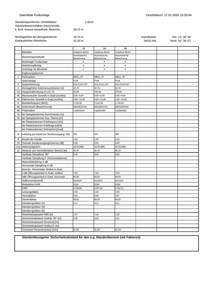
Datenblatt Funkanlage Druckdatum: 17.01.2020 13:33:04 Standortspezifischer Umfeldfaktor: Standortbereichsfaktor (Horiz/Vertik): k. Entf. Grenze kontrollierb. Bereichs: 1,0019 30,70 m Montagehöhe der Bezugsantenne: Gebäudehöhe-/Masthöhe: 32,70 m 42,20 m Koordinaten (WGS 84) 13 14 15 Betreiber Vodafone Berlin Vodafone Berlin Vodafone Berlin Bewertungsmethode Automatische Berechnung Automatische Berechnung Automatische Berechnung Beantragte Funkanlage X X X Gebührenpflichtig X X X Unterliegt 26./BlmSchV X X X Ergänzungsbereich 1 Funksystem MB21_VF MB21_VF MB21_VF Funk Funk Funk 2 Antennentyp Systemkennung GUL21A1-C67 GUL21A2-C67 GUL21A3-C67 3 Montagehöhe Antennenunterkante [m] 32,70 32,70 32,70 4a Hauptstrahlrichtung N.ü.O. [°] 30,00 150,00 270,00 4b Mechanischer Downtilt in Grad (von/bis) 0,00 / 6,00 0,00 / 6,00 0,00 / 6,00 4c Elektrischer Downtilt in Grad (von/bis) 2,00 / 14,00 2,00 / 14,00 2,00 / 14,00 5 Betriebsfrequenz [MHz] 2.110,30 2.110,30 2.110,30 6a Antennenart (Bezeichnung) 80010622V01 80010622V01 80010622V01 6b Polarisation x-polarisiert x-polarisiert x-polarisiert 7a bei Spiegelantennen Durchmesser [m] 7b bei Spiegelantennen bzw. Fläche [m²] bei Radarantennen Pulsfrequenz [Hz] bei Radarantennen Pulslänge [uSek] bei Radarantennen Drehwinkel [Grad] 8 Leistung pro Kanal am Senderausgang [W] 104 104 104 9 Anzahl der Kanäle 1,00 1,00 1,00 0,40 0,50 0,60 18,39 [dBi] 18,39 [dBi] 18,39 [dBi] 30,70 30,70 30,70 9,40 9,40 9,40 3 dB-Öffnungswinkel in Grad, vertikal 7,00 7,00 7,00 3dB-Öffnungswinkel in Grad, horizontal 66,00 66,00 66,00 Hüllkurvendynamik konstant konstant konstant Modulation KHM GSM GSM GSM EIRP 6.546,86 6.397,84 6.252,21 Leistungsfaktor 2,00 2,00 2,00 Verlustfaktor 0,91 0,89 0,87 Gewinnfaktor 69,02 69,02 69,02 Dämpfungsfaktor (V) 0,11 0,11 0,11 Sicherheitsabstand HSR [m] 7,27 7,18 7,10 Sicherheitsabstand Vertikal -90° [m] 2,46 2,43 2,41 61,00 61,00 61,00 10 Verluste Senderausgang/Antenne [dB] 11a Antennengewinn 12 Abstand zum kontrollierbaren Bereich [m] Vertikale Dämpfung -90° Vertikale Dämpfung 0° (Horizontalebene) Materialdämpfung in dB Horizontale Dämpfung in dB berücks. Horizontaler Winkel in Grad Dämpfungsfaktor (H) Dämpfungsfaktor (D) Sicherheitsabstand Horizontal [m] Sicherheitsabstand Vertikal 0° [m] Grenzwert Personenschutz [V/m] Standortbezogener Sicherheitsabstand für den o.g. Standortbereich (mit Faktoren): Ost: 13° 39' 38'' Nord: 52° 36' 52''


